Click here to view the complete list of archived articles
This article was originally published in the
Spring 2005 issue of Methods & Tools
Click
here to reach PDF area
Agile Development with ICONIX Process
Doug Rosenberg, Matt Stephens and Mark
Collins-Cope
http://www.softwarereality.com/AgileDevelopment.jsp
ICONIX Process is a minimalist, use-case driven object modeling process that is well suited to agile Java development. It uses a core subset of UML diagrams, and provides a reliable method of getting from use cases to source code in as few steps as possible. It’s described in the book Agile Development with ICONIX Process (more information can be found about the book on http://www.softwarereality.com/AgileDevelopment.jsp).
Because the process uses a minimal set of steps, it’s also well suited to agile development, and can be used in tandem with test-driven development (TDD) to help "plug the gaps" in the requirements.
The book describes the use case driven analysis and design process in detail, with lots of examples using UML, C# and Java. However, for this book excerpt, we focus on how to combine unit testing with up-front UML modeling, to produce a really rigorous software design. The process begins with the use cases and UML diagrams, then moves into Java source code via Junit.
Test-Driven Development with ICONIX Process
In this book, we put together an example system using "vanilla" test-driven development (TDD). We then repeat the example using a mixture of TDD and ICONIX modeling. In the excerpt below, we show this aspect of agile ICONIX development.
The premise behind TDD is that you write the unit tests first, then write the code to make the tests pass. The process of doing this in theory lets you design the code as you write it. However, we prefer a more rigorous, "higher-level" design approach, which we describe here.
How Agile ICONIX Modeling and TDD Fit Together
There’s a prevailing opinion in the agile world that "formal" up-front design modeling and TDD are mutually exclusive. However, we’re going to demonstrate that TDD can in fact be particularly effective with an up-front design method like ICONIX Process.
ICONIX Process takes the design to a low level of detail via sequence diagrams—one sequence diagram for each use case. These diagrams are used to allocate behaviors to the class diagrams. The code can then be written quickly without much need for refactoring. However, the coding stage is still not exactly a brainless activity. The programmer (who, incidentally, should also be actively involved in the design modeling stage) still needs to give careful thought to the low-level design of the code. This is an area to which TDD is perfectly suited.
The "Vanilla" Example Repeated Using ICONIX Modeling and TDD
Let’s pause and rewind, then, back to the start of the TDD example that we covered in the previous chapter. To match the example, we’re going to need a system for travel agent operatives to place hotel bookings on behalf of customers.
To recap, the following serves as our list of requirements for this initial release:
Create a new customer.
Create a hotel booking for a customer.
Retrieve a customer (so that we can place the booking).
Place the booking.
As luck would have it, we can derive exactly one use case from each of these requirements (making a total of four use cases). For this example, we’ll focus on the first use case, "Create a New Customer".
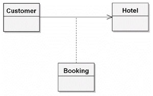
Let’s start by creating a domain model that contains the various elements we need to work with, as shown in Figure 1. As you can see, it’s pretty minimal at this stage. As we go through analysis, we discover new objects to add to the domain model, and we possibly also refine the objects currently there. Then, as the design process kicks in, the domain model swiftly evolves into one or more detailed class diagrams.
Figure 1. Domain model for the hotel booking example
The objects shown in Figure 1 are derived simply by reading through our four requirements and extracting all the nouns. The relationships are similarly derived from the requirements. "Create a hotel booking for a customer," for example, strongly suggests that there needs to be a Customer object that contains Booking objects. In a real project, it might not be that simple—defining the domain model can be a highly iterative process involving discovery of objects through various means, including in-depth conversations with the customer, users, and other domain experts. Defining and refining the domain model is also a continuous process throughout the project’s life cycle.
If some aspect of the domain model turns out to be wrong, we change it as soon as we find out, but for now, it gives us a solid enough foundation upon which to write our use cases.
Here’s the use case for "Create a New Customer":
Basic Course: The system shows the Customer Details page, with a few default parameters filled in. The user enters the details and clicks the Create button; the system validates that all the required fields have been filled in; and the system validates that the customer name is unique and then adds the new Customer to the database. The system then returns the user to the Customer List page.
Alternative Course: Not all the required fields were filled in. The system informs the user of this and redisplays the Customer Details form with the missing fields highlighted in red, so that the user can fill them in.
Alternative Course: A customer with the same name already exists. The system informs the user and gives them the option to edit their customer details or cancel.
This use case probably has more user interface details than you’re used to seeing in a use case. This is a characteristic of "ICONIX-style" use cases: they’re quite terse, but they are very closely tied to the domain model, and to the classes that you’ll be designing from.
Next, we draw a robustness diagram – i.e. a picture version of the use case (see Figure 2).
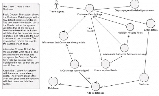
Figure 2. Robustness diagram for the Create a New Customer use case
A robustness diagram shows conceptual relationships between objects. Because it’s an "object drawing" of the use case text, it occupies a curious space halfway between analysis and design. Nevertheless, mastering robustness analysis is the key to creating rigorous designs from clear, unambiguous use cases.
The robustness diagram shows three types of object:
Boundary objects (a circle with a vertical line at the left) – these represent screens, JSP pages and so forth
Entities (a circle with a horizontal line at the bottom) – these are the data objects (e.g. Customer, Hotel Booking)
Controllers (a circle with an arrow-head at the top) – these represent actions that take place between other objects (i.e. Controllers are the verbs)
Note that in the book, we take the "Create a New Customer" use case and robustness diagram through several iterations, using the robustness diagram to polish up and "disambiguate" the use case text. For brevity we just show the finished version here).
Sequence Diagram for "Create a New Customer"
Now that we’ve disambiguated our robustness diagram (and therefore also our use case text), let’s move on to the sequence diagram (see Figure 3).

Figure 3. Sequence diagram for the Create a New Customer use case
More Design Feedback: Mixing It with TDD
The next stage is where the ICONIX+TDD process differs slightly from vanilla ICONIX Process. Normally, we would now move on to the class diagram, and add in the newly discovered classes and operations. We could probably get a tool to do this part for us, but sometimes the act of manually drawing the class diagram from the sequence diagrams helps to identify further design errors or ways to improve the design; it’s implicitly yet another form of review.
We don’t want to lose the benefits of this part of the process, so to incorporate TDD into the mix, we’ll write the test skeletons as we’re drawing the class diagram. In effect, TDD becomes another design review stage, validating the design that we’ve modeled so far. We can think of it as the last checkpoint before writing the code (with the added benefit that we end up with an automated test suite).
So, if you’re using a CASE tool, start by creating a new class diagram (by far the best way to do this is to copy the existing domain model into a new diagram). Then, as you flesh out the diagram with attributes and operations, simultaneously write test skeletons for the same operations.
Here’s the important part: the tests are driven by the controllers and written from the perspective of the Boundary objects.
If there’s one thing that you should walk away from this article with, then that’s definitely it! The controllers are doing the processing—the grunt work—so they’re the parts that most need to be tested (i.e., validated that they are processing correctly). Restated: the controllers represent the software behavior that takes place within the use case, so they need to be tested. However, the unit tests we’re writing are black-box tests (aka closed-box tests)—that is, each test passes an input into a controller and asserts that the output from the controller is what was expected. We also want to be able to keep a lid on the number of tests that get written; there’s little point in writing hundreds of undirected, aimless tests, hoping that we’re covering all of the failure modes that the software will enter when it goes live. The Boundary objects give a very good indication of the various states that the software will enter, because the controllers are only ever accessed by the Boundary objects. Therefore, writing tests from the perspective of the Boundary objects is a very good way of testing for all reasonable permutations that the software may enter (including all the alternative courses). Additionally, a good source of individual test cases is the alternative courses in the use cases. (In fact, we regard testing the alternative courses as an essential way of making sure all the "rainy-day" code is implemented.)
Okay, with that out of the way, let’s write a unit test. To drive the tests from the Control objects and write them from the perspective of the Boundary objects, simply walk through each sequence diagram step by step, and systematically write a test for each controller. Create a test class for each controller and one or more test methods for each operation being passed into the controller from the Boundary object.
Looking at the sequence diagram in Figure 3, we should start by creating a test class called CustomerDetailsValidatorTest, with two test methods, testCheckRequiredFields() and testCustomerNameUnique():
package iconix;
import junit.framework.*;
public class CustomerDetailsValidatorTest extends TestCase {
public CustomerDetailsValidatorTest(String testName) {
super(testName);
}
public static Test suite() {
TestSuite suite = new
TestSuite(CustomerDetailsValidatorTest.class);
return suite;
}
public void testCheckRequiredFields() throws Exception {
}
public void testCustomerNameUnique() throws Exception {
}
}
At this stage, we can also draw our new class diagram (starting with the domain model as a base) and begin to add in the details from the sequence diagram/unit test (see Figure 4).
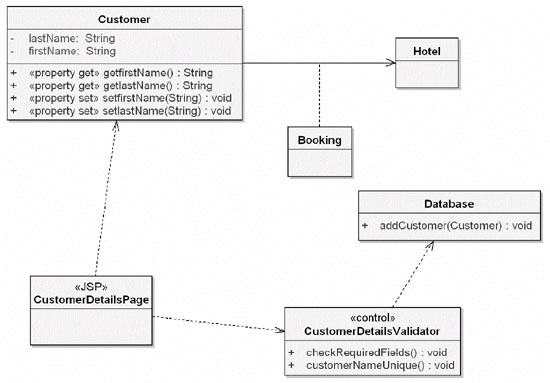
Figure 4. Beginnings of the detailed class diagram
As you can see in Figure 4, we’ve filled in only the details that we’ve identified so far using the diagrams and unit tests. We’ll add more details as we identify them, but we need to make sure that we don’t guess at any details or make intuitive leaps and add details just because it seems like a good idea to do so at the time.
TIP: Be ruthlessly systematic about the details you add (and don’t add) to the design.
In the class diagram in Figure 4, we’ve indicated that CustomerDetailsValidator is a <<control>> stereotype. This isn’t essential for a class diagram, but it does help to tag the control classes so that we can tell at a glance which ones have (or require) unit tests.
Next, we want to write the actual test methods. Remember, these are being driven by the controllers, but they are written from the perspective of the Boundary objects and in a sense are directly validating the design we’ve created using the sequence diagram, before we get to the "real" coding stage. In the course of writing the test methods, we may identify further operations that might have been missed during sequence diagramming.
Our first stab at the testCheckRequiredFields() method looks like this:
public void
testCheckRequiredFields() throws Exception {
List fields = new ArrayList();
Customer customer = new Customer (fields);
boolean allFieldsPresent = customer.checkRequiredFields();
assertTrue("All required fields should be present",
allFieldsPresent);
}
Naturally enough, trying to compile this initially fails, because we don’t yet have a CustomerDetailsValidator class (let alone a checkRequiredFields() method). These are easy enough to add, though:
public class
CustomerDetailsValidator {
public CustomerDetailsValidator (List fields) {
}
public boolean checkRequiredFields() {
return false; // make the test fail initially.
}
}
Let’s now compile and run the test. Understandably, we get a failure, because checkRequiredFields() is returning false (indicating that the fields didn’t contain all the required fields):
CustomerDetailsValidatorTest
.F.
Time: 0.016
There was 1 failure:
1) testCheckRequiredFields(CustomerDetailsValidatorTest)
junit.framework.AssertionFailedError:
All required fields should be present
at CustomerDetailsValidatorTest.testCheckRequiredFields(
CustomerDetailsValidatorTest.java:21)
FAILURES!!!
Tests run: 2, Failures: 1, Errors: 0
However, where did this ArrayList of fields come from, and what should it contain? In the testCheckRequiredFields() method, we’ve created it as a blank ArrayList, but it has spontaneously sprung into existence—an instant warning sign that we must have skipped a design step. Checking back, this happened because we didn’t properly address the question of what the Customer fields are (and how they’re created) in the sequence diagram (see Figure 3). Let’s hit the brakes and sort that out right now (see Figure 5).
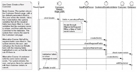
Figure 5. Revisiting the sequence diagram to add more detail
Revisiting the sequence diagram identified that we really need a Map (a list of name/value pairs that can be looked up individually by name) and not a sequential List.
Now that we’ve averted that potential design mishap, let’s get back to the CustomerDetailsValidator test. As you may recall, the test was failing, so let’s add some code to test for our required fields:
public void
testCheckRequiredFields() throws Exception {
Map fields = new HashMap();
fields.put("userName", "bob");
fields.put("firstName", "Robert");
fields.put("lastName", "Smith");
Customer customer = new Customer(fields);
boolean allFieldsPresent = customer.checkRequiredFields();
assertTrue("All required fields should be present",
allFieldsPresent);
}
A quick run-through of this test shows that it’s still failing (as we’d expect). So now let’s add something to CustomerDetailsValidator to make the test pass:
public class
CustomerDetailsValidator {
private Map fields;
public CustomerDetailsValidator (Map fields)
{
this.fields = fields;
}
public boolean checkRequiredFields() {
return fields.containsKey("userName") &&
fields.containsKey("firstName") &&
fields.containsKey("lastName");
}
}
Let’s now feed this through our voracious unit tester:
CustomerDetailsValidatorTest
..
Time: 0.016
OK (2 tests)
The tests passed!
Summing Up
Hopefully this article gave you a taster of what’s involved in combining a code-centric, unit test-driven design methodology (TDD) with an UML-based, use case-driven methodology (ICONIX Process). In Agile Development with ICONIX Process, we take this example further, showing how to strengthen the tests and the use cases by adding controllers for form validation, and by writing unit tests for each of the alternative courses ("rainy day scenarios") in the use cases.
References
Agile Development with ICONIX Process: People,
Process, and Pragmatism
by Doug Rosenberg, Mark Collins-Cope, Matt Stephens
Publisher: Apress, ISBN: 1590594649
Test Driven Development: http://www.testdriven.com