|
Software Development Magazine - Project Management, Programming, Software Testing |
|
Scrum Expert - Articles, tools, videos, news and other resources on Agile, Scrum and Kanban |
Understanding Use Case Modeling
Sinan Si Alhir, http://sites.google.com/site/salhir/
Introduction
Following the "method wars" of the 1970s and 1980s, the Unified Modeling Language (UML) emerged from the unification that occurred in the 1990s within the information systems and technology industry. Unification was lead by Rational Software Corporation and Three Amigos, Grady Booch, James Rumbaugh, and Ivar Jacobson. The UML gained significant industry support from various organizations via the UML Partners Consortium and was submitted to and adopted by the Object Management Group (OMG) as a standard (November 17, 1997).
The UML is an evolutionary general-purpose, broadly applicable, tool-supported, and industry-standardized modeling language for specifying, visualizing, constructing, and documenting the artifacts of a system-intensive process. The language is broadly applicable to different types of systems (software and non-software), domains (business versus software), and methods and processes. The UML enables and promotes (but does not require nor mandate) a use-case-driven, architecture-centric, iterative, and incremental process that is object oriented and component based. The UML enables the capturing, communicating, and leveraging of knowledge: models capture knowledge (semantics), architectural views organize knowledge in accordance with guidelines expressing idioms of usage, and diagrams depict knowledge (syntax) for communication.
System development may be characterized as problem solving, including understanding or conceptualize and representing a problem, solving the problem by manipulating the representation of the problem to derive a representation of the desired solution, and implementing or realizing and constructing the solution. This process is very natural and often occurs subtly and sometimes unconsciously in problem solving.
Models are complete abstractions of systems. Models are used to capture knowledge (semantics) about problems and solutions. Architectural views are abstractions of models. Architectural views are used to organize knowledge in accordance with guidelines expressing idioms of usage. Diagrams are graphical projections of sets of model elements. Diagrams are used to depict knowledge (syntax) about problems and solutions. Within the fundamental UML notation, concepts are depicted as symbols and relationships among concepts are depicted as paths (lines) connecting symbols.
Use case modeling from the user model view (also known as the use case or scenario view), which encompasses a problem and solution as understood by those individuals whose problem the solution addresses, involves use case diagrams to depict the functionality of a system.
Use Case Diagrams
To successfully apply use case diagrams, we must first understand the types of elements used in use case diagrams.
Actors
Actor classes are used to model and represent roles for "users" of a system, including human users and other systems. Actors are denoted as stick person icons. They have the following characteristics:
- Actors are external to a system.
- Actors interact with the system. Actors may use the functionality provide by the system, including application functionality and maintenance functionality. Actors may provide functionality to the system. Actors may receive information provided by the system. Actors may provide information to the system.
- Actor classes have actors instances or objects that represent specific actors.
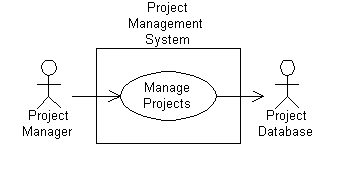
Figure 1 shows a project management system with a project manager actor and a project database actor. The project manager is a user who is responsible for ensuring the success of project and uses the system to manage projects. The project database is a system that is responsible for housing project management data.

Figure 1
Use Cases
Use case classes are used to model and represent units of functionality or services provided by a system (or parts of a system: subsystems or classes) to users. Use cases are denoted as ellipses or ovals. They may be enclosed by a system boundary or rectangle labeled with the name of the containing system. They have the following characteristics:
- Use cases are interactions or dialogs between a system and actors, including the messages exchanged and the actions performed by the system. Use cases may include variants of these sequences, including alternative and exception sequences.
- Use cases are initiated by actors and may involve the participation of numerous other actors. Use cases should provide value to at least one of the participating actors.
- Use cases may have extension points that define specific points within an interaction at which other use cases may be inserted.
- Use case classes have use case instances or objects called scenarios that represent specific interactions. Scenarios represent a singe sequence of messages and actions.
Figure 1 shows a project management system which provides the functionality to manage projects in which the project manager and project database participate.
|
Methods & Tools Software Testing Magazine The Scrum Expert |


