|
Software Development Magazine - Project Management, Programming, Software Testing |
|
Scrum Expert - Articles, tools, videos, news and other resources on Agile, Scrum and Kanban |
Database Modelling in UML - Page 2
By Geoffrey Sparks, www.sparxsystems.com.au
The UML Data Model Profile
The Data Model Profile is a proposed UML extension (and currently under review - Jan 2001) to support the modelling of relational databases in UML. It includes custom extensions for such things as tables, data base schema, table keys, triggers and constraints. While this is not a ratified extension, it still illustrates one possible technique for modelling a relational database in the UML.
Tables
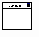
A table in the UML Data Profile is a class with the "Table" stereotype, displayed as above with a table icon in the top right corner.
Columns
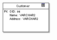
Database columns are modelled as attributes of the "Table" class. For example, the figure above shows some attributes associated with the Customer table. In the example, an object id has been defined as the primary key, as well as two other columns, Name and Address. Note that the example above defines the column type in terms of the native DBMS data types.
Behaviour
So far we have only defines the logical (static) structure of the table; in addition we should describe the behaviour associated with columns, including indexes, keys, triggers, procedures & etc. Behaviour is represented as stereotyped operations.
The figure below shows our table above with a primary key constraint and index, both defined as stereotyped operations:
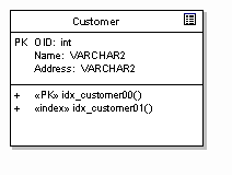
Note that the PK flag on the column 'OID' defines the logical primary key, while the stereotyped operation ""PK" idx_customer00" defines the constraints and behaviour associated with the primary key implementation (that is, the behaviour of the primary key).
Adding to our example, we may now define additional behaviour such as triggers, constraints and stored procedures as in the example below:
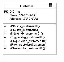
The example illustrates the following possible behaviour:
- A primary key constraint (PK);
- A Foreign key constraint (FK);
- An index constraint (Index);
- A trigger (Trigger);
- A uniqueness constraint (Unique);
- A stored procedure (Proc) - not formally part of the data profile, but an example of a possible modelling technique; and a
- Validity check (Check).
Using the notation provided above, it is possible to model complex data structures and behaviour at the DBMS level. In addition to this, the UML provides the notation to express relationships between logical entities.
Relationships
The UML data modelling profile defines a relationship as a dependency of any kind between two tables. It is represented as a stereotyped association and includes a set of primary and foreign keys.
The data profile goes on to require that a relationship always involves a parent and child, the parent defining a primary key and the child implementing a foreign key based on all or part of the parent primary key.
The relationship is termed 'identifying' if the child foreign key includes all the elements of the parent primary key and 'non-identifying' if only some elements of the primary key are included.
The relationship may include cardinality constraints and be modelled with the relevant PK - FK pair named as association roles. Figure 4 illustrates this kind of relationship modelling using UML.
The Physical Model
UML also provides some mechanisms for representing the overall physical structure of the database, its contents and deployed location. To represent a physical database in UML, use a stereotyped component as in the figure below:
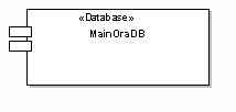
A component represents a discrete and deployable entity within the model. In the physical model, a component may be mapped on to a physical piece of hardware (a 'node' in UML).
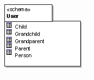
To represent schema within the database, use the "schema" stereotype on a package. A table may be placed in a "schema" to establish its scope and location within a database.
Mapping from the Class Model to the Relational Model
Having described the two domains of interest and the notation to be used, we can now turn our attention as to how to map or translate from one domain to the other. The strategy and sequence presented below is meant to be suggestive rather than proscriptive - adapt the steps and procedures to your personal requirements and environment.
1. Model Classes
Firstly we will assume we are engineering a new relational database schema from a class model we have created. This is obviously the easiest direction as the models remain under our control and we can optimise the relational data model to the class model. In the real world it may be that you need to layer a class model on top of a legacy data model - a more difficult situation and one that presents its own challenges. For the current discussion will focus on the first situation. At a minimum, your class model should capture associations, inheritance and aggregation between elements.
2. Identify persistent objects
Having built our class model we need to separate it into those elements that require persistence and those that do not. For example, if we have designed our application using the Model-View-Controller design pattern, then only classes in the model section would require persistent state.
3. Assume each persistent class maps to one relational table
A fairly big assumption, but one that works in most cases (leaving the inheritance issue aside for the moment). In the simplest model a class from the logical model maps to a relational table, either in whole or in part. The logical extension of this is that a single object (or instance of a class) maps to a single table row.
4. Select an inheritance strategy
Inheritance is perhaps the most problematic relationship and logical construct from the object-oriented model that requires translating into the relational model. The relational space is essentially flat, every entity being complete in its self, while the object model is often quite deep with a well-developed class hierarchy.
The deep class model may have many layers of inherited attributes and behaviour, resulting in a final, fully featured object at run-time. There are three basic ways to handle the translation of inheritance to a relational model:
- Each class hierarchy has a single corresponding table that contains all the inherited attributes for all elements - this table is therefore the union of every class in the hierarchy. For example, Person, Parent, Child and Grandchild may all form a single class hierarchy, and elements from each will appear in the same relational table;
- Each class in the hierarchy has a corresponding table of only the attributes accessible by that class (including inherited attributes). For example, if Child is inherited from Person only, then the table will contain elements of Person and Child only;
- Each generation in the class hierarchy has a table containing only that generation's actual attributes. For example, Child will map to a single table with Child attributes only
There are cases to be made for each approach, but I would suggest the simplest, easiest to maintain and less error prone is the third option. The first option provides the best performance at run-time and the second is a compromise between the first and last.
The first option flattens the hierarchy and locates all attributes in one table - convenient for updates and retrievals of any class in the hierarchy, but difficult to authenticate and maintain. Business rules associated with a row are hard to implement, as each row may be instantiated as any object in the hierarchy. The dependencies between columns can become quite complicated. In addition, an update to any class in the hierarchy will potentially impact every other class in the hierarchy, as columns are added, deleted or modified from the table.
The second option is a compromise that provides better encapsulation and eliminates empty columns. However, a change to a parent class may need to be replicated in many child tables. Even worse, the parental data in two or more child classes may be redundantly stored in many tables; if a parent's attributes are modified, there is considerable effort in locating dependent children and updating the affected rows.
The third option more accurately reflects the object model, with each class in the hierarchy mapped to its own independent table. Updates to parents or children are localised in the correct space. Maintenance is also relatively easier, as any modification of an entity is restricted to a single relational table also. The down side is the need to re-construct the hierarchy at run-time to accurately re-create a child class's state. A Child object may require a Person member variable to represent their model parentage. As both require loading, two database calls are required to initialise one object. As the hierarchy deepens, with more generations, the number of database calls required to initialise or update a single object increases.
It is important to understand the issues that arise when you map inheritance onto a relational model, so you can decide which solution is right for you.
|
Methods & Tools Software Testing Magazine The Scrum Expert |


